We developed a device named MEPAP(Multipurpose and source Electricity Generator with Air Purifier) which reduces air pollution and generates electricity from various sources.The growing demand for electrical energy and increasing air pollution around the globe is the main factor that driven my research.More than 80 percent of our energy today comes from burning fossil fuels, which is both harmful to our environment and unsustainable as well. Our invention will help to solve the energy crisis by improving the efficiency of electromagnetic energy-harvesting systems, vibration energy-harvesting systems , wind energy-harvesting systems, thermal energy harvesting system and air cleanser all in a single project.MEPAP AIR CLEANSER IS AN AIR PURIFIER WHICH PURIFIES AIR FROM THE SOURCE (VEHICLES AND FACTORIES EXHAUST)WHERE IT IS PRODUCED.IT IS MADE TO REDUCE THE AIR POLLUTION. The compact purifier is an apt solution for the increasing pollution. The Active Oxidization Cell with its self cleaning abilities keeps the purification process on, while the 360º air flow guards us from harmful impurities by distributing healthy air.
MEP ELECTRICITY GENERATOR GENERATES ELECTRICITY WITH THE HELP OF VIBRATRION(Piezoelectric Materials) AND ELECTROMAGNETIC RADIATION(with the help of MetaMaterials) ELECTROMAGNETIC induction [inductive coupling(power density is proportional to d, q, 1/d^3)] and wind energy( from purifier where mini turbine is connected with dynamo) AND ALSO THERMOELECTRIC ENERGY (power density=25µW/cm^2)
THE GIVEN BELOW IS A DETAILED ABOUT MY INVENTION MULTIPURPOSE AND MULTISOURCE ELECTRICITY GENERATOR INTEGRATED WITH AIR PURIFIER .
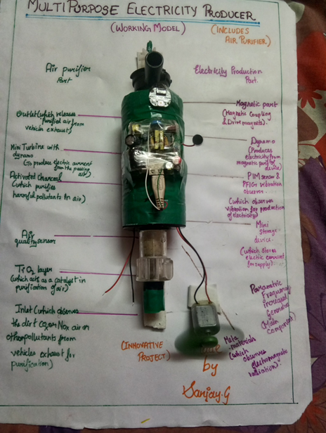
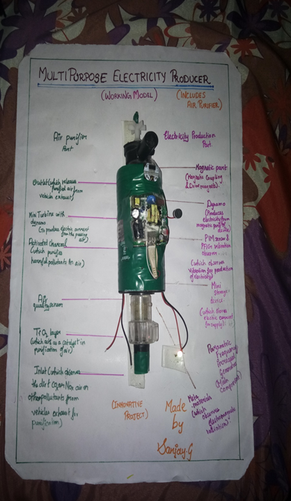
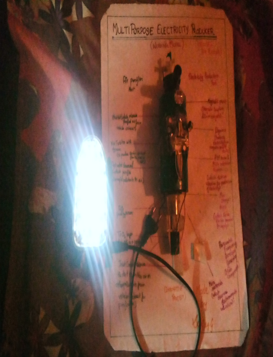
Multipurpose ELECTRICITY Producer Integrated With air purifier (MEPAP)
MEPAP's AIR PURIFYING PART
MEPAP AIR CLEANSER IS AN AIR PURIFIER WHICH PURIFIES AIR FROM THE SOURCE (VEHICLES AND FACTORIES EXHAUST)WHERE IT IS PRODUCED. IT IS MADE TO REDUCE THE AIR POLLUTION.
The compact purifier is an apt solution for the increasing pollution. The Active Oxidization Cell with its self cleaning abilities keeps the purification process on, while the 360º air flow guards us from harmful impurities by distributing healthy air.
FEATURES:
Active shield;
The purification process eliminates sub-micron respirable particles and infection carrying microbes in the air.
Active Carbon Filter;
The most advanced technology filters out bad odor, toxic gases and other harmful gases including VOCs (Volatile Organic Compounds) from the air you breathe in. The carbon filters have excellent absorbent qualities to soothe respiratory discomforts by eliminating irritants in the air.
ICC (Improved Catalytic Converter):
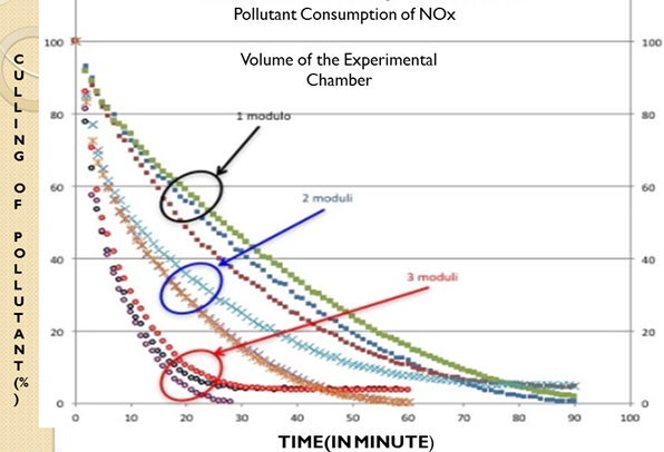
Catalytic converters, having expensive metals namely platinum-palladium and rhodium as the catalysts, are fitted into automobiles for reducing emission of poisonous gases. As the exhaust passes through the catalytic converter, unburnt hydrocarbons are converted into carbon dioxide and water, and carbon monoxide and nitric oxide are changed to carbon dioxide and nitrogen gas, respectively.
To overcome from cost and reducing the rare metal usage the project made the drive to develop an alternate source of oxidation catalyst for oxidation reaction and thus reduces the NOx and HC emissions. The substrate selected in this project is wash coat technology employed by using the silicon dioxide and alumina with silica. The catalytic converter is constructed with inner/outer shell construction supported with cones and flanges. The initial emission readings are conducted in the experimental engine. This catalytic converter reduces the harmful pollutant more efficiently and at a lower cost than the conventional catalytic converter.
Honeycomb Active Carbon Filter;
The carbon filters have excellent absorbent qualities to eliminate repulsive smell, toxic gases and other odor, leaving behind fresh and pure air to breathe.
HEPA (High Efficiency Particulate Air Filter) Type Filter;
The HEPA type filter removes airborne pollutants and eliminates ultra-fine particles like bacteria, pollen, and mould, which cannot be done by other air purifiers.
Anion Generator;
The technology ensures that the air you breathe has no positive ions, leaving you rest assured of living in a no impurities zone. Negative ions produced by purifier bind themselves with airborne pollutants and removes them from the air thereby creating a fresh and cleaner environment.
Air Pollution sensors;
Air pollution sensors are devices that detect and monitor the presence of air pollution in the surrounding area. They can be used for both indoor and outdoor environments. These sensors can be built at home, or bought from certain manufactures. Although there are various types of air pollution sensors, and some are specialized in certain aspects, the majority focuses on five components: ozone, particulate matter, carbon monoxide, sulfur dioxide, and nitrous oxide.
FUTURE PLAN FOR AIR PURIFIER PART:
Carbon Separator and Collector: Carbon dioxide is considered a major reason for global warming. The element jeopardizes people’s health, threatens national security, and endangers basic human needs. Yet, it also holds great promise as a fuel of the future.
The carbon dioxide splitter, which consists of copper and tin.
The splitter has an atomic layer of tin in order to trap the energy that would be lost if copper is utilized as an electrode. It also has a thin membrane between the cathode and anode to improve the reaction.
The splitter can open windows to solving the problem of storing energy from renewable sources by turning it straight into liquid fuel.The process of splitting is efficient and carbon-neutral. It is already a well-known method of producing fuel without increasing the level of carbon dioxide in the atmosphere. CO2 is split into oxygen and carbon monoxide.
Carbon monoxide can be incorporated with hydrogen to create synthetic carbon-based fuel. CO2 is taken out of the atmosphere without being put back in, which produces clean fuel.
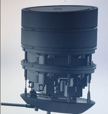
INTERIOR DESIGN: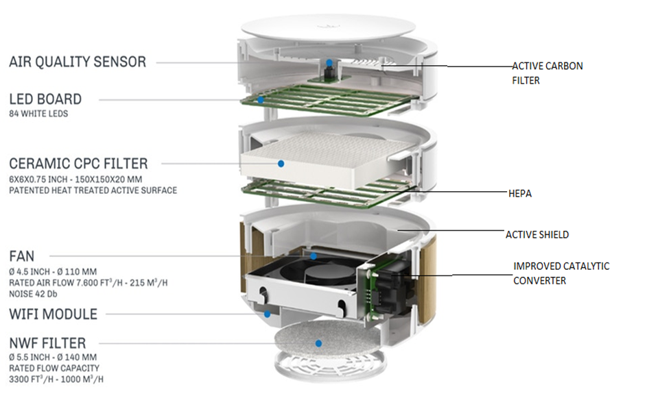
PROTOTYPE DESIGN IN AUTODESK:
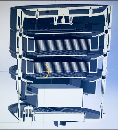
CARBON LAYER:
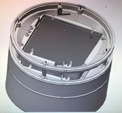 ACTIVATED CARBON WITH CERAMIC TiO2.
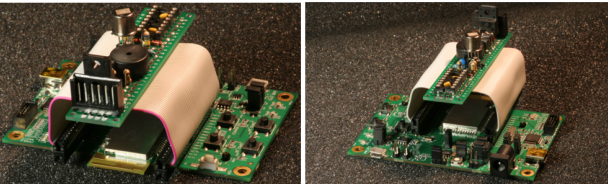
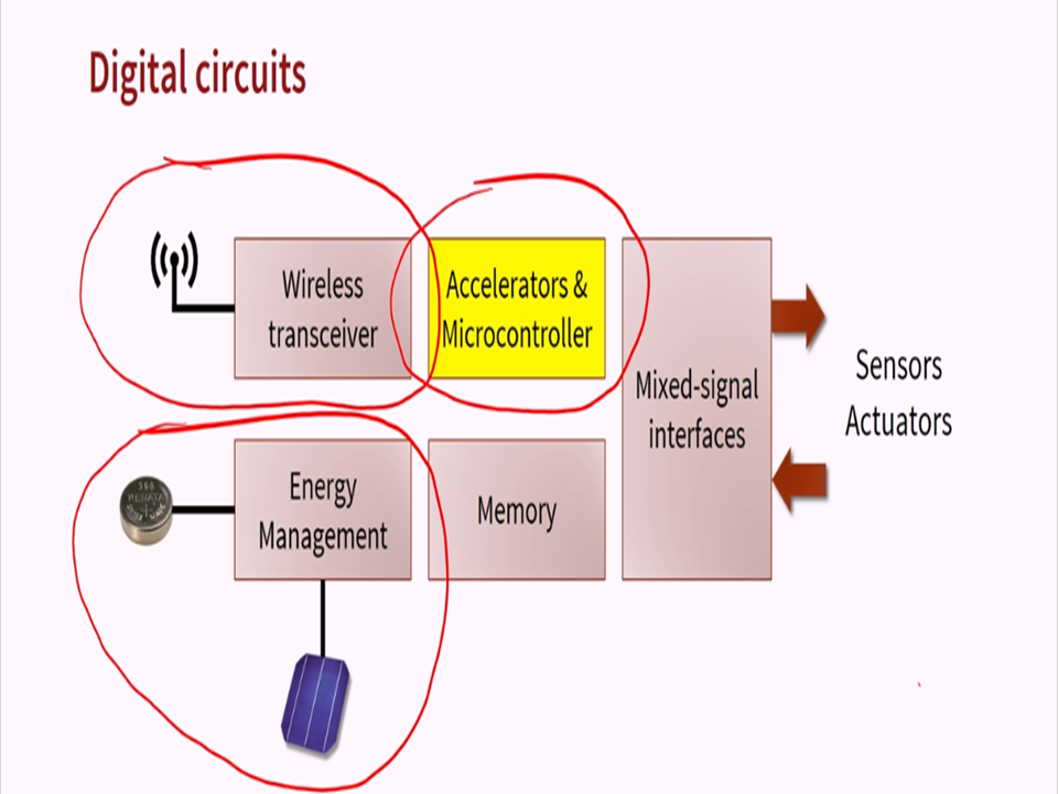
The main advanced chip:

WITH MEPAP AIR CLEANSER WE CAN GET RID OF

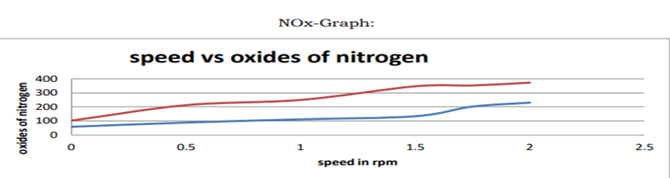
RESEARCH TEST;
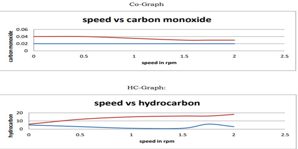
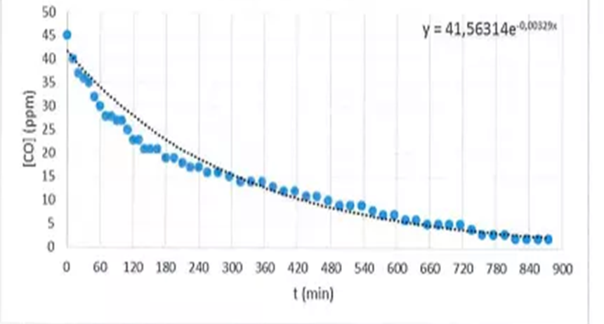
RESEARCH TEST(for CO):
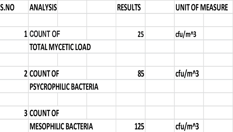
IMPACT ON BACTERIAS:
RESEARCH TEST ON FORMALDEHYDE: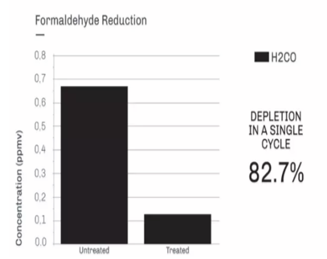
MEPAP ELECTRICITY PRODUCTION PART
MEPAP ELECTRICITY GENERATOR GENERATES ELECTRICITY WITH THE HELP OF VIBRATRION(Piezoelectric Materials) AND ELECTROMAGNETIC RADIATION(with the help of MetaMaterials) ELECTROMAGNETIC induction [inductive coupling(power density is proportional to d, q, 1/d^3)] and wind energy( from purifier where mini turbine is connected with dynamo) AND ALSO THERMOELECTRIC ENERGY (power density=25µW/cm^2).
ELECTRICITY from VIBRATRION:
MEPAP ELECTRICITY GENERATOR could produce enough electricity from random, ambient vibrations to power a wristwatch, pacemaker, wireless sensor , phones etc..,
MEPAP are highly efficient at providing renewable electrical power from arbitrary, non-periodic vibrations. This type of vibration is a byproduct of traffic driving on bridges, machinery operating in factories and humans moving their limbs.
In two of the sub generators present in PFIG(Parametric Frequency Increased Generators), the energy conversion is performed through electromagnetic induction, in which a coil is subjected to a varying magnetic field. This is a process similar to how large-scale generators in big power plants operate. It also uses piezoelectric material, which is a type of material that produces charge when it is stressed. This version has applications in infrastructure health monitoring. The generators could one day power bridge sensors that would warn inspectors of cracks or corrosion before human eyes could discern problems.
Power Density= 4 µW/cm^2.
MECHANISM AND APPLICATIONS:
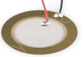
It contain a resonator which is used to amplify the vibration source, and a transducer device which changes the energy from the vibrations into electrical energy. The transducer consists of a magnet and coil of a piezoelectric crystal.
A number of crystals can emit an electric current when compressed or they can change shape when an electric charge is employed. This piezoelectric effect is used in ultrasound and sonar devices, as well as energy harvesting.
Piezoelectric generators utilize thin casings or beams made of piezoelectric crystals as a transducer mechanism. When a crystal is placed under strain by the kinetic energy of the vibration, a small quantity of current is produced because of the piezoelectric effect. These mechanisms are generally straightforward with few moving parts, and they have a very long service life, making them the most prevalent technique of harvesting the energy from vibrations. It is fabricated by MEMS process.
This device uses a freely rotating, unconventional brass rotor with an implanted magnet, and multiple PZT beams with a magnet on each beam.
As the magnet on the rotor draws near one of the beams, the magnets repel each other and deflects the beam, pulling the beam in a process that is described as frequency up-conversion. The gradual rate of a rotating wrist is changed into a higher frequency oscillation. This device is more efficient than a standard electromagnetic harvester, as such as those used in self-powered watches.
Another application, which is in the early stages of development, desires to use the vibrations generated during aircraft flight to power the electronics on the plane that currently depend on on batteries. Such a system would produce a reliable energy source, and reduce maintenance, since batteries would not need to be replaced and piezoelectric systems have a long service life. This system uses a resonator, which permits the airflow to produce a high amplitude steady tone. This is the same principle that is used in many wind instruments by converting the airflow furnished by the musician into a loud steady tone. This tone is used as the vibration that is transformed from kinetic to electric energy by the piezoelectric generator.
ELECTRICITY from ELECTROMAGNETIC RADIATION:
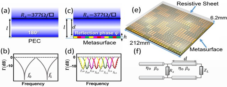
Electromagnetic energy harvesting based on the "full absorption concept." This involves the use of metamaterials that can be tailored to produce media that neither reflects nor transmits any power—enabling full absorption of incident waves at a specific range of frequencies and polarizations Since the inception of collecting and harvesting electromagnetic energy, classical dipole patch antennas have been used. "Now, my technology introduces 'metasurfaces' that are much better energy collectors than classical antennas. microstrip patch antennas are used because of their low profile, light weight, and planar structure for RF harvesting.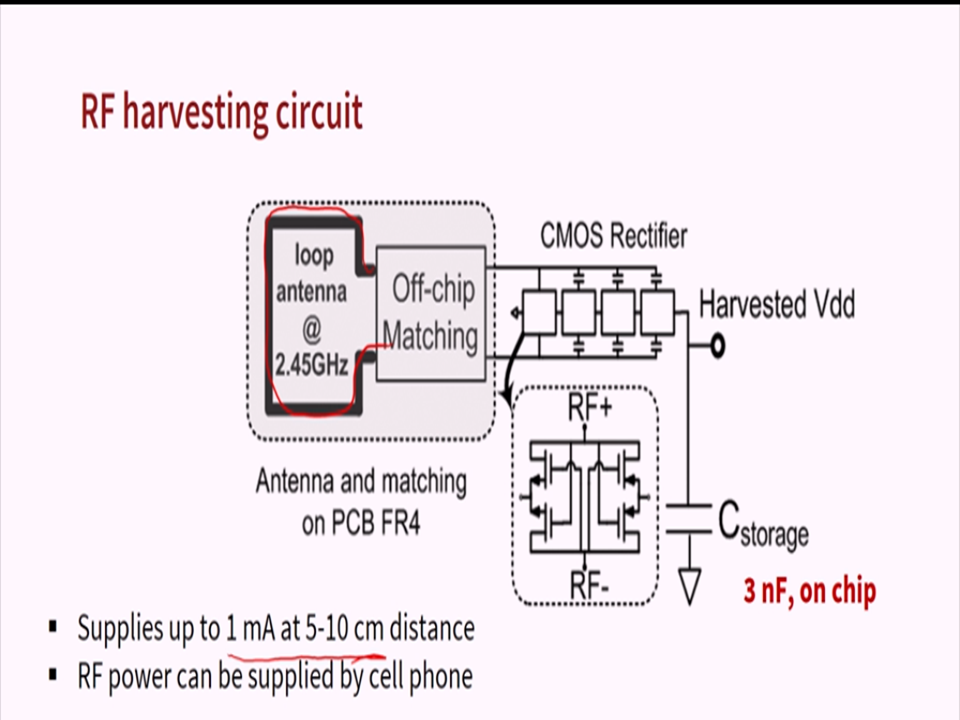
Metasurfaces are formed by etching the surface of a material with an elegant pattern of periodic shapes. The particular dimensions of these patterns and their proximity to each other can be tuned to provide "near-unity" energy absorption. This energy is then channeled to a load through a conducting path that connects the metasurface to a Electromagnetic energy collector.
We can also channel the absorbed energy into a load, rather than having the energy dissipate in the material as was done in previous works.?Other key applications include "wireless power transfer—directly adaptable to power remote devices such as RFID devices and tags or even remote devices in general.
The technology can also be extended to the infrared spectra.
Power Density= 25µW/cm^2.
Metasurfaces:

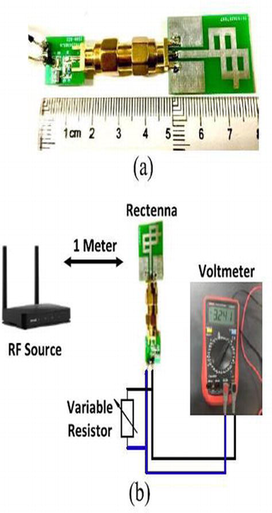
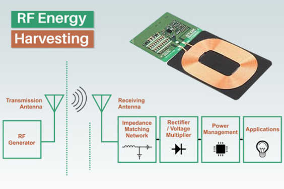
ELECTRICITY from ELECTROMAGNETIC RADIATION(RF):
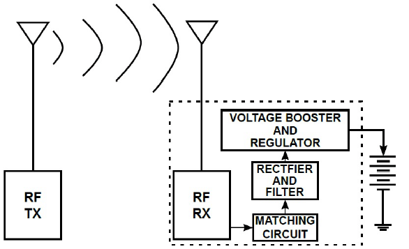
Wi-Fi signals are made of radio waves. Receiving antennas can wirelessly harvest electromagnetic radiation in the Wi-Fi (2.4 GHz and 5.9 GHz), global satellite positioning (1.58 GHz and 1.22 GHz), the cellular communications fourth-generation (4G) (1.7 GHz and 1.9 GHz), and Bluetooth (2.4 GHz) bands and convert the energy from these electromagnetic waves to alternating current (AC). The AC electricity is then sent to the rectifier, which converts it to direct current (DC) electricity.

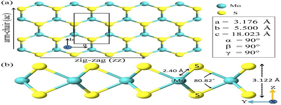
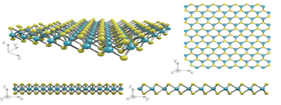
Using a rectifier made from a molybdenum disulfide (MoS2) layer that is only 3 atoms thick. At this thickness, the MoS2 behaves differently than the bulk material — the atoms rearrange themselves when exposed to certain chemicals. This means the material can behave like a switch, changing from a semiconductor to metallic structure. The MoS2 creates what’s called a Schottky diode, a junction of semiconductor and metal. The diode described in their paper can convert signals at higher frequencies because the structure reduces the extra energy stored by certain materials used in electronics, known as parasitic capacitance. The researchers’ design reduces parasitic capacitance by an order of magnitude compared to current flexible rectifiers, meaning they can capture the previously elusive high-frequency Wi-Fi band radio waves.
ENERGY FROM TERAHERTZ(will implment in future.):
Terahertz waves are electromagnetic radiation with a frequency somewhere between microwaves and infrared light. Also known as “T-rays,” they are produced by almost anything that registers a temperature, including our own bodies and the inanimate objects around us.
Terahertz waves are pervasive in our daily lives, and if harnessed, their concentrated power could potentially serve as an alternate energy source. However, to date there has been no practical way to capture and convert them into any usable form.
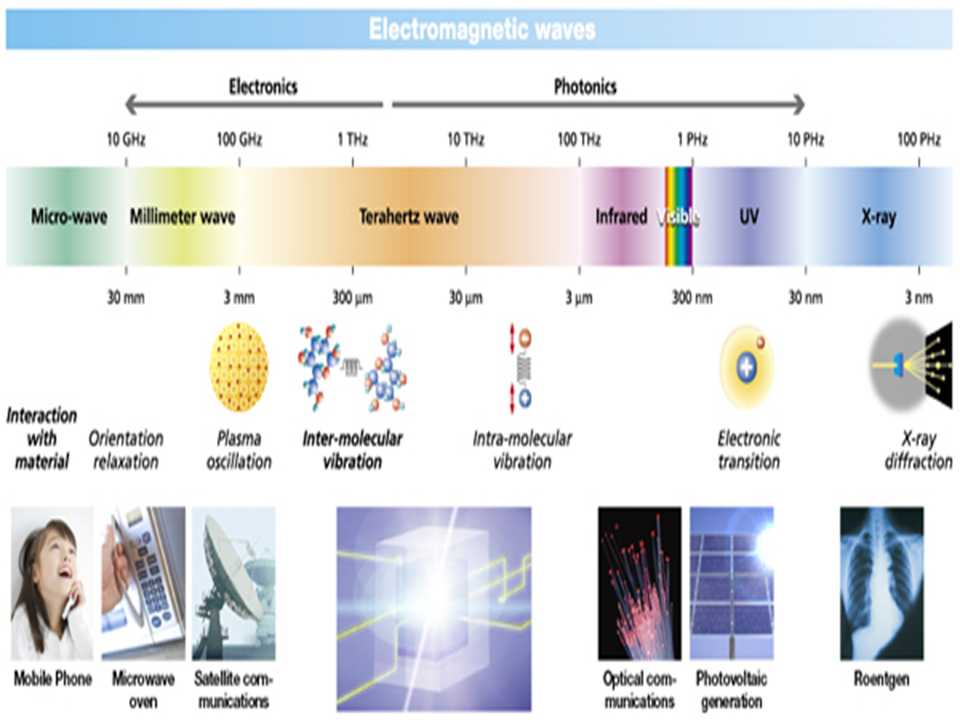
MEPAP device would be able to convert terahertz waves into a direct current in future, a form of electricity that powers many household electronics.
This design (referred from MIT ) takes advantage of the quantum mechanical, or atomic behavior of the carbon material graphene. They found that by combining graphene with another material, in this case, boron nitride, the electrons in graphene should skew their motion toward a common direction. Any incoming terahertz waves should “shuttle” graphene’s electrons, like so many tiny air traffic controllers, to flow through the material in a single direction, as a direct current.
Rectifiers, devices that are designed to convert electromagnetic waves from their oscillating (alternating) current to direct current.
Most rectifiers are designed to convert low-frequency waves such as radio waves, using an electrical circuit with diodes to generate an electric field that can steer radio waves through the device as a DC current.
Solar Energy:
Photovoltaic (PV) solar panels use the sun's power to create a flow of electricity. This is the most widely adopted method of harvesting solar energy today. These panels, which range in size from a few square centimeters to a few square meters, are constructed from many PV cells arranged in an intricate matrix. Intuitively, the larger the surface area available for sunlight to penetrate the PV cells, the more solar energy that gets harvested.
Each PV solar cell is generally made up of a compound semiconductor wafer structure, which can either be a monocrystalline or polycrystalline structure. The structure's two thin semiconductor wafers, one P-type and one N-type, are each grown separately. The two wafers are placed on top of each other, and the natural reaction that occurs between the two semiconductor types creates a depletion zone that reaches an equilibrium point, without generating any electricity. Due to the PV cell, when light photons pass through and connect with the semiconductor wafers, their interaction releases enough energy to create an equilibrium disruption in the depletion region. That action subsequently creates a brief flow of electricity. However, because of the constant presence of light, this interaction occurs continuously and can produce massive amounts of electrical energy.
The power produced by a single photon interaction replicates across the entire surface of the PV cell. It's compounded into a whole panel of solar cells. This minor interaction in the depletion zone can be repeated and multiplied, resulting in a significant amount of electricity. PV solar arrays, however, produce DC power. To be integrated with modern power transmission technology, such as the outlets in your home, this DC energy must be converted to AC power using an inverter. There are a variety of proprietary iterations of this fundamental technology that seek to optimize the efficiency of each PV cell on a molecular level, the assembly of the panel, and the panel's ability to be integrated into a larger solar array.
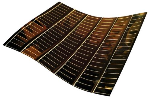
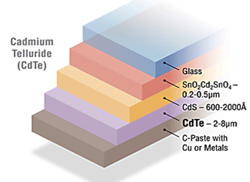
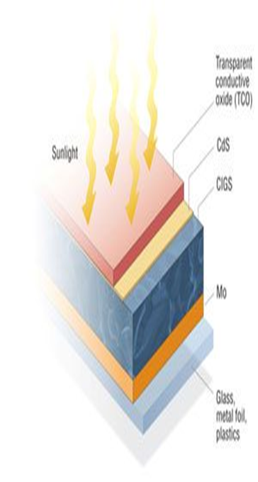
Thin-film solar cell, type of device that is designed to convert light energy into electrical energy (through the photovoltaic effect) and is composed of micron-thick photon-absorbing material layers deposited over a flexible substrate.
Cadmium telluride thin-films have a peak recorded efficiency of more than 22.1 percent (the percentage of photons hitting the surface of the cell that are transformed into an electric current). By 2014 cadmium telluride thin-film technologies had the smallest carbon footprint and quickest payback time of any thin-film solar cell technology on the market. This is the reason why I used Cadmium telluride thin-film in MEPAP.
Power Density= 1000µW/cm^2
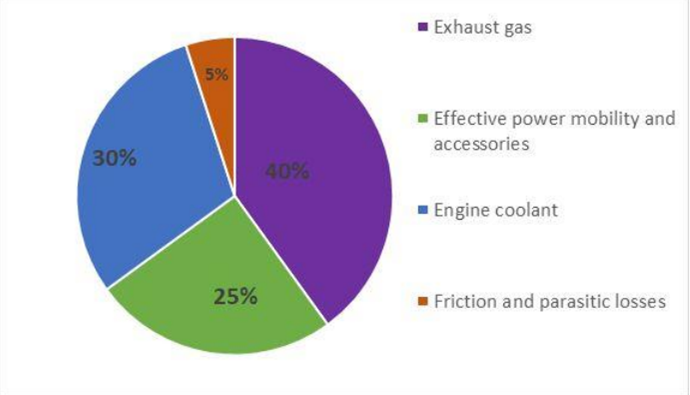
Energy Harvesting from a Vehicle’s Exhaust System Using Thermoelectric Generator Module(TEG):
The efficiency in an internal combustion engine ranges from 25% to 35%. About 50% - 85% of the overall energy loss in a combustion engine is heat, which is either cooled away by the vehicle’s radiator or blown out with the exhaust gases. The other losses take place in bearings and gear boxes. This energy is never put into use again and therefore is called “waste heat”. Even if a small fraction of the waste heat could be turned into useful energy again, it would be a step to the right direction of improving fuel economy.
TEG in MEPAP is a solid stated device which works on the principle of ‘Seebeck effect’.
They are found in solar energy systems like solar panels, solar hot water system, biomass power applications, energy power plants and solar pond systems .Installing a TEG with MEPAP is easy and very beneficial as it has some advantages like small in size, it has no vibrations, makes less or no noise while operating, it generally requires less or no maintenance. And major advantage is that it is using free thermal energy and converting into useful electrical energy. A thermoelectric module consists of many thermo elements connected in electrical channel in series to increase the operating voltage and to increase the thermal conductivity they are connected in parallel. According to a research the conversion of this waste heat into electricity results to an increase of fuel efficiency about 20% . A TEG in MEPAP works on the principle of a Seebeck effect. Two metallic strips, made of different metals and joined at the ends to form a loop. If the junctions are kept at different temperatures then there is an electric current in the loop and the emf developed is called the SEEBECK emf or thermo emf and the current can be used to power a load.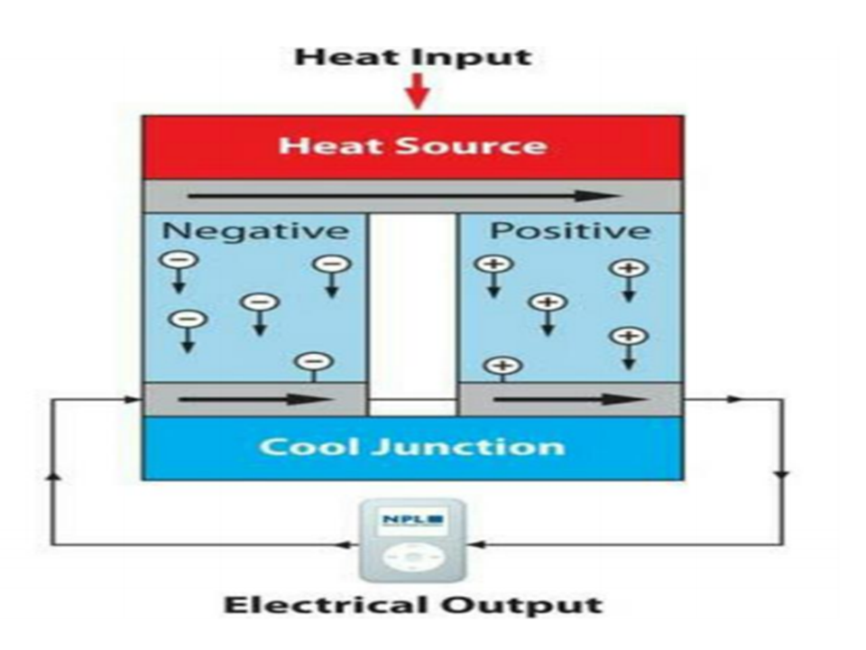
The TEG in MEPAP structure is sandwiched with the thermoelectric material which is then sandwiched by the heat exchanger plates at their ends respectively. The two heat exchangers remains at different temperatures, one at high temperature and the other at lower temperature and called the hot side and cold side. A thermally insulated layer is present between metal heat exchanger and material of a TEG in MEPAP. The p type and n type materials are connected by the metal electrically. A TEG in MEPAP consists of a two sides, one is cold and other is hot side. The hotter side derives the electrons in n type leg towards the cold side which pass through the metallic connection and then passes into the p type leg, hence develops current. Larger the temperature difference between cold side and hot side, larger value of emf will produce.
TEG Power Generation Calculation :
The equation involved in calculation of the performance of a TEG
Z = α 2 / kR
Z is a figure of merit of thermoelectric material, R is the electric resistivity
k is a thermal conductivity and
α is a Seebeck coefficient which is
α = ∆V / ∆T,
Thermoelectric materials(TE) are used in automobiles, power plants, space satellite, etc. Thermoelectric materials can be characterized according to the structure and composition. They can be classified as - chalcogenide , clathrates, skutterudites, half-heusler, oxides and silicides. The most common thermoelectric materials are the alloys of chalcogenide. The calcogenide materials are popular for their use with (Bi2Te3) and (PbTe).Thermoelectric materials made with Bi2Te3, Se and Sb for temperature use are economical. PbTe has better thermo electric properties at temperature range 500-600 ⁰C and has been used by NASA as a radioactive thermo electric generator (RTG’s) . The stability of a TE material is very important as it should not oxidize within the operating temperature when exposed in air .But nowadays, automobile industries are focusing on bismuth telluride for constructing a TEG in MEPAP.
High charge mobility and small band gaps are the properties of two heavy elements Bi and Te and Bulk alloys of PbTe have a zT value of 0.7 at 467 ⁰C. When SrTe and PbTe are doped with Na, zT value was 2.2 at 642 ⁰C .Skutterudites (MX3) have a lower thermal conductivity due to its complex crystal structure has large voids. CoSb3 based skutterudites are versatile in accepting various actinides, lanthanides, alkalis and alkaline earth metals to be used in void filling and thermal conductivity of skutterudites lowers as the size decreases .Compounds of half heuslers are intermetallic compounds which are thermally stable, having high thermal conductivity and corresponding seebeck coefficient. The lattice thermal conductivity of these compounds reduces having nano structures due to phonon scattering . SiGe alloys are used for high temperature applications because of having very low degradation upto 1000 ⁰C. When compared to their bulk alloys, nanostructured SiGe alloys have higher zT value. Bulk Si0.8 Ge0.2 have zT value of 1 and 0.6 for n type and p type respectively. There is an improvement in zT value when nanocomposite thermoelectric materials are used .
HARVESTING WIND ENERGY(HEW Module):
The present invention relates to a combination air purifier and wind generator. The combination air purifier and wind generator includes a wind-receiving unit installed on a central shaft for driving an electric generator mounted in housing, and an air purifier. The wind-receiving unit includes a governor fixed to an upper end of the central shaft, a spherical blower installed in the middle of the central shaft, and planar magnetic rotary plates installed at a lower end of the central shaft for receiving both artificial and natural winds. Lower magnets are attached to the top of the housing while upper magnets having the same polarity as the lower magnets are attached to the bottoms of the magnetic rotary plates to face the lower magnets. The air purifier includes two air inlets; one air outlet; a copper net, a silver net and a hard charcoal/zeolite net disposed within the air purifier for purifying air introduced there into; and a blower interposed between the silver net and the hard charcoal/zeolite net.
Even though the intensity of the wind increases, the shaft of the generator is prevented from being accelerated beyond a predetermined speed so that any damage to the generator can be avoided and its life can be prolonged, and which includes a multi-stage wind-receiving unit for causing the shaft to be easily rotated even with the gentle natural wind and the artificial wind from the blower so as to enhance the electricity generation.
HEW Module consist of electric generator installed in a box-type housing, a central shaft protruding beyond the top of the box-type housing and having a lower end with a gear coupled thereto for engaging with a gear of the electric generator and transmitting a rotational force, and a wind-receiving unit coupled to the central shaft. The wind-receiving unit includes a governor fixed to an upper end of the central shaft, a spherical blower disposed below the governor, and planar magnetic rotary plates disposed below the blower for receiving both artificial and natural winds. The governor includes a plurality of cylinders of which one ends are fixed to the central shaft, a plurality of wind cups of which one ends are slidably installed within the respective cylinders, and springs connected with the inner ends of the wind cups for elastically supporting them. Lower magnets are attached to the top of the box-type housing, and upper magnets having the same polarity as the lower magnets are disposed on the bottoms of the respective magnetic rotary plates to face down toward the lower magnets.
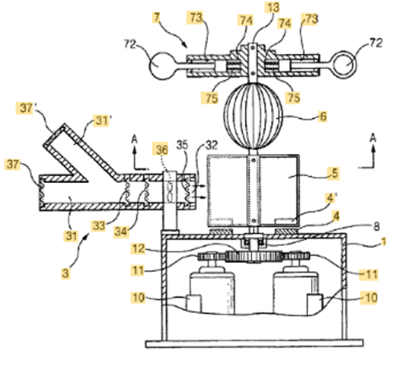
FIG. 1 is a sectional view of a combination air purifier and wind generator according to the present invention.
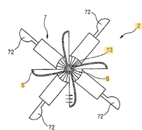
FIG. 2 is a section view taken along line A—A of FIG. 1.
BRIEF DESCRIPTION OF DRAWINGS:
Hereinafter, a preferred embodiment of a combination air purifier and wind generator according to the present invention will be described in detail with reference to the accompanying drawings.
FIGS. 1 and 2 are sectional views of a combination air purifier and magnet-type wind generator according to the present invention. Reference numeral 1 designates a box-type housing, 2 designates a wind-receiving unit, 3 designates an air purifier, and 10 designates an electric generator.
Each of the electric generators 10 is a conventional model for converting mechanical energy into electrical energy. A shaft of the electric generator 10 is coupled with a gear 11.
The electric generator 10 is installed within the box-type housing 1 made of steel frame and plate, or the like. The gear 11 of the electric generator 10 is engaged with and rotated together with a gear 12 coupled with a lower end of a central shaft 13 which penetrates through the center of a top surface of the box-type housing 1 and is positioned in the box-type housing 1. Thus, the gear 11 connected to components for generating electricity, such as a coil and a magnet that are not shown in the figures, within the electric generator 10 converts the mechanical energy into the electrical energy.
The wind-receiving unit 2 installed on the central shaft 13 includes three wind-resistant bodies: a governor 7 fixed to an upper end of the central shaft 13, a spherical blower 6 disposed below the governor, and planar magnetic rotary plates 5 disposed below the blower 6 for receiving both artificial and natural winds.
The governor 7 fixed to the upper end of the central shaft 13 is a horizontal centrifugal rotary body and includes a plurality of cylinders 73 of which one ends are fixed to the central shaft 13, a plurality of wind cups 72 of which one ends are slidably installed within the respective cylinders 73, and springs 75 connected with the inner ends of the wind cups 72 and inner walls 74 of the cylinders 73 for elastically supporting them.
The blower 6 installed in the middle of the central shaft 13 takes the shape of a sphere defined by a plurality of grouped winglets and can obtain a rotational force even with gentle winds generated in all directions. Further, since the blower 6 is disposed in the middle of the central shaft, it can serve to provide a starting force to the central shaft 13 upon existence of the gentle wind while keeping the balance of the central shaft 13, thereby preventing the central shaft 13 from stopping.
Each of the planar magnetic rotary plates 5 installed at a lower portion of the central shaft 13 is made in the form of a rectangular bucket as shown in FIG. 2. Upper magnets 4′ are attached to the bottoms of the respective magnetic rotary plates. Repulsive forces are produced between the upper magnets 4′ and lower permanent magnets 4 (20,000 gauss or higher) that have the same polarity as the upper magnets and are attached to the top of the box-type housing 1, and thus, a levitation phenomenon occurs therebetween. Accordingly, weights of all the components installed on the central shaft 13 become zero, so that the magnetic rotary plates can be easily rotated even with the gentle wind by means of a rotational action resulting from the repulsive forces between the magnets having the same polarity. Consequently, the rotational ability of the magnetic rotary plates can be improved even under any windy conditions. Particularly, the magnetic rotary plates are constructed to be forcibly rotated with the artificial wind discharged from a blower 36 of the air purifier 3 to be described later, even in the gentle natural wind or windless state.
Moreover, as shown in FIG. 2, the wind cups 72 of the governor 7 and the magnetic rotary plates 5 are staggered so that the wind sequentially and consecutively encounters the wind cups 72 and the magnetic rotary plates 5. Thus, a continuous rotational force is transmitted to the central shaft 13.
The air purifier 3 is fixedly installed on a side of the top of the box-type housing 1 and is Y-shaped by including two air inlets 31, 31′ and one air outlet 32. One of the air inlets 31 is horizontally in line with the air outlet 32 while the other air inlet 31′ is formed to incline upward, so that a wind can be generated due to a change in ambient airflow resulting from drawn air streams and a discharged air stream. Further, a copper net 33, a silver net 34 and a hard charcoal/zeolite net 35 for purifying the polluted air are disposed to be spaced apart from one another at predetermined intervals within the air purifier so that the polluted air is caused to pass through them and to be purified. The blower 36 is interposed between the silver net 34 and the hard charcoal/zeolite net 35 so that the air is forced to be drawn and discharged. Mosquito nets 37, 37′ can be installed at the air inlets 31, 31′ to prevent insects from entering the air purifier.
Reference numeral 8, which has not yet been explained, designates a bearing for ensuring smooth rotation of the central shaft 13.
Next, the operation of the combination air purifier and wind generator according to the present invention will be described.
When the box-type housing 1 of the combination air purifier and wind generator is installed at a desired location such as the interior of a room or a roadside, a no-load state suitable for rotation of the central shaft 13 is achieved by means of the repulsive forces between the upper magnets 4′ in the magnetic rotary plates 5 and the lower magnets 4 attached to the box-type housing 1. Thus, even though a very gentle wind encounters the blower 6, the wind cups 72 of the governor 7 and the magnet rotary plates 5, the central shaft 13 immediately begins to be rotated and is further accelerated by the action of the repulsive forces between the lower and upper magnets 4, 4′. Accordingly, the desired electricity can be easily obtained through the electric generators 10.
In order to reduce loads and cause the rotational speed of the central shaft 13 to reach a normal rotational speed in a short time upon initial rotation of the central shaft 13, the wind cups 72 of the governor 7 are maintained in a state where they are pulled toward the central shaft 13 by the springs 75. The wind cups 72 are kept in the initial starting state without any change in their state so as to facilitate the rotation of the central shaft 13 until rated electricity is provided through normal electricity generation.
The initial rotation of the central shaft is facilitated even with the gentle wind by means of the repulsive forces between the lower and upper magnets 4, 4′, the inward positioned state of the wind cups 72, and the spherical blower 6. Further, the magnetic repulsive forces and the inward positioned state of the wind cups 72 continuously assist the central shaft 13, which has begun to be rotated, to cause its rotation speed to reach the rotational speed at which the desired rated electricity can be generated.
Meanwhile, if the intensity of the wind is increased in a state where the rotational speed of each electric generator 10 reaches a normal rotational speed, the rotational speed of the central shaft 13 is also increased and thus the electric generator may be burdened with an overload.
In order to protect the electric generator 10 against the overload, if the central shaft 13 is rotated with a rotational force larger than a predetermined rotational force, the wind cups 72 of the governor 7 are urged outward from the center of the central shaft 13 by centrifugal forces to reduce its rotational force. On the contrary, if the rotational force of the central shaft 13 begins to be reduced, the wind cups 72 are pulled toward the central shaft by means of the restoring forces of the springs 75 so as to reduce the centrifugal forces. Therefore, it is possible to always maintain the normal rotational speed of the central shaft 13.
Meanwhile, in the very gentle natural wind state or the windless state, the blower 36 of the air purifier 3 is operated using either electric power, which has been generated by the electric generators 10 and then stored, or separate electric power. With the operation of the blower 36, the ambient polluted air is caused to be introduced into the air inlets 31, 31′. This causes a change in airflow thereabouts which in turn generates a wind. The introduced polluted air is purified by passing through the copper net 33, the silver net 34 and the hard charcoal/zeolite net 35, which are disposed within the air purifier. The purified air is discharged and then causes the magnetic rotary plates 5 to be rotated as shown in FIG. 2. As the magnetic rotary plates 5 are rotated, the blower 6 and the governor 7 installed above the magnetic rotary plates are rotated together therewith to increase the rotational force. Finally, the central shaft 13 operates the electric generators 10 so that the electricity is generated.
STORAGE SYSTEMS :
The hybrid energy-storage system(HESS) contains two supercapacitors of different sizes and a switching circuit. An adaptive-learning switching algorithm controls the switching circuit. This algorithm predicts the available source energy and the period that the sensor node will remain in the high-energy area. The algorithm dynamically switches between the supercapacitors according to available ambient RF, Vibration, Solar, EM and Thermal energy. Extensive simulation and experiments evaluated the proposed method. The proposed system showed 40% and 80% efficiency over single supercapacitor system in terms of the amount of harvested energy and sensor coverage.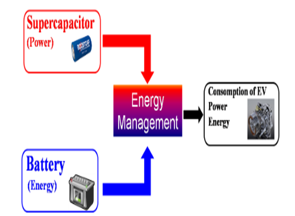
In a HESS typically one storage (ES1) is dedicated to cover “high power” demand, transients and fast load fluctuations and therefore is characterized by a fast response time, high efficiency and high cycle lifetime. The other storage (ES2) will be the “high energy” storage with a low self-discharge rate and lower energy specific installation costs .
Main advantages of a HESS are:
Reduction of total investment costs compared to a single storage system (due to a decoupling of energy and power, ES2 only has to cover average power demand)
Increase of total system efficiency (due to operation of ES2 at optimized, high efficiency operating points and reduction of dynamic losses of ES2)
Increase of storage and system lifetime (optimized operation and reduction of dynamic stress of ES2).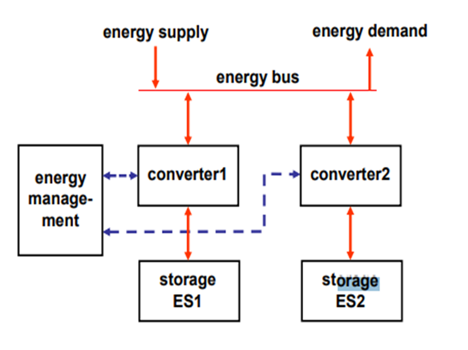
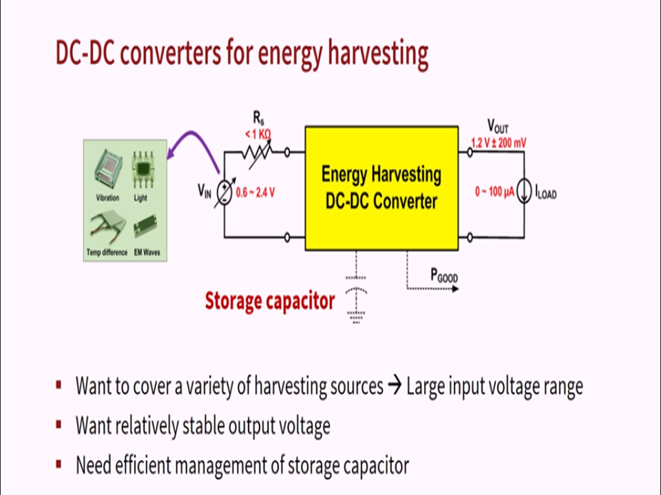
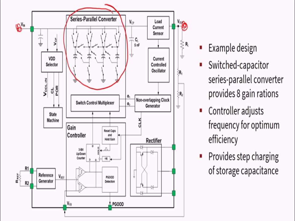
Energy storage coupling architecture in HESS used in MEPAP:
The coupling architecture in MEPAP consists of two DC/DC-converters. Here the parallel converter topology is very common. The additional DC/DC-converter associated with the “high-power” storage is in charge of the voltage regulation of the DC-bus. It helps to operate the “high-power” storage in a broader voltage band, and hereby the available storage capacity is better utilized.
Frequency decoupling used in MEPAP is well suited for real-time applications. It is accomplished by a simple low-pass filter or by advanced filter concepts based on wavelet or Fourier transform. The low frequency component supplies the set-point value of the power controller of ES2, the high frequency component is covered by ES1.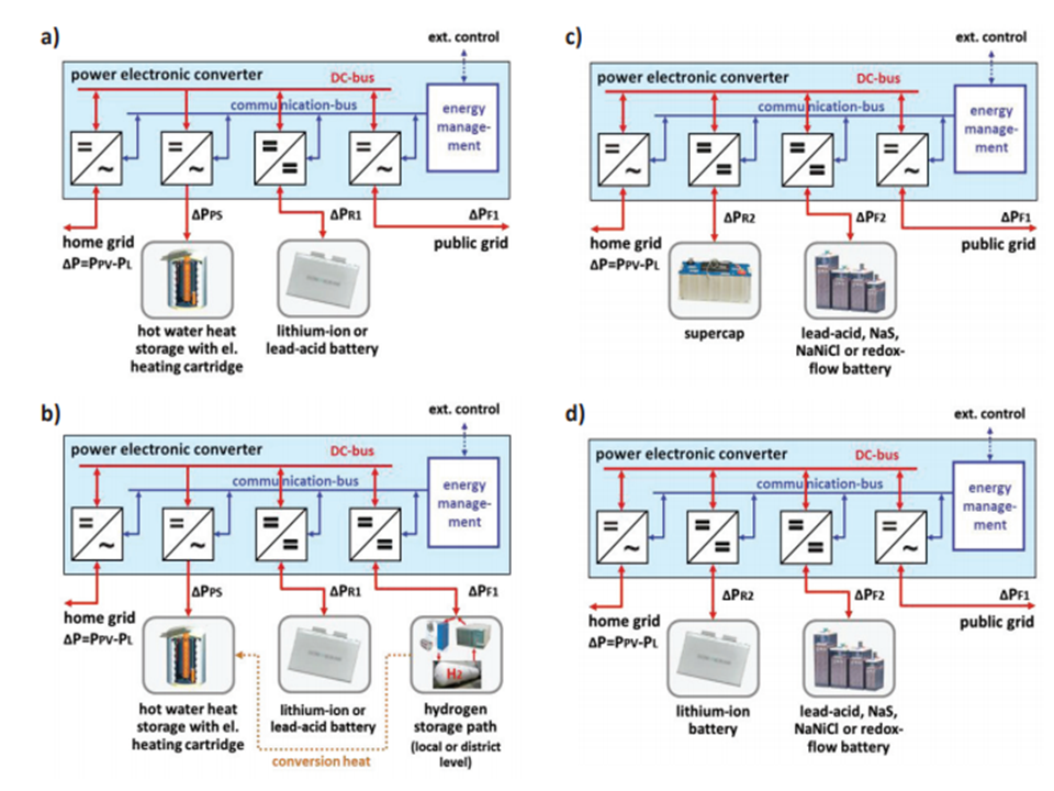
CONCLUSION:
Therefore with MEPAP we can prevent the depletion of fossil fuels which are used in large quantities for the production of energy as MEPAP uses various sources to produce electrical energy.
MEPAP can also reduce air pollution abruptly as it purifies the polluted air from the source itself.
We hope to achieve a sustainable environment and best solution award for our project.